Marine CSEM (Controlled Source EM) for Direct Hydrocarbon Detection
| For the past few years, marine CSEM (Controlled Source Electromagnetic) exploration has been applied for direct hydrocarbon detection after three dimensional seismic survey and before drilling. More recently, it has been applied after two dimensional seismic survey to delineate possible high resistive target in order to save the exploration cost. . |
| 3JTech has developed a new marine CSEM technology using Solenoid transmitter or a Combination of Wire and Solenoid transmitter (for more information: 该 Email 地址已受到反垃圾邮件插件保护。要显示它需要在浏览器中启用 JavaScript。 |
 |
| VEL Numerical Modeling: |
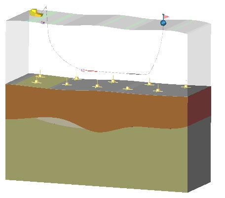
| The following three figures are numerical modeling results using vertical electrical line source (VEL). The transmitting current through the VEL is at 500 amperes with 10 mil-seconds ramp time and 5 seconds duration. The length of VEL is one kilo-meter. The separation between the transmitter and receiver is one kilo-meter. The depth to the seabed is two kilo-meters. The resistivity of the first layer below the seabed is one ohm-meter. The resistivity of the target layer is 200 ohm-meter while the thickness of that is 100 meters. Figure 2 and figure 3 show the vertical electric field and the azimuthal magnetic field respectively after the current is turned off for different thickness of the first layer for the marine earth model and VEL system configuration shown in Figure 1. |
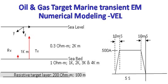 |
| Figure 1: Marine earth model and VEL system configuration for numerical Modeling. |
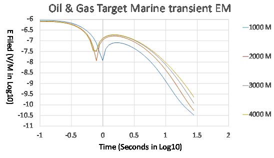 |
| Figure 2 shows the vertical electrical field after the current is turned off for different thickness of the first layer for the marine earth model and VEL system configuration shown in Figure 1. |
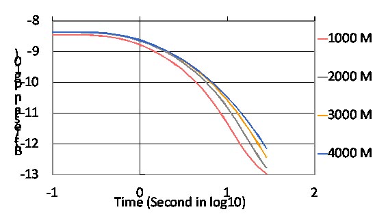 |
| Figure 3 shows the azimuthal magnetic field after the current is turned off for different thickness of the first layer for the marine earth model and VEL system configuration shown in Figure 1. |
| Solenoid Numerical Modeling |
| The following four figures are numerical modeling results using horizontal solenoid source. The transmitting current through the Solenoid is at 500 amperes with 10 mil-seconds ramp time and 5 seconds duration. The length of the solenoid is two hundred meters. The marine earth model is the same as the one for VEL modeling. Figure 5, 6 and 7 are the inline magnetic field for the different TX and RX separations at 8, 6 and 4 kilo-meters respectively after the current is turned off for different thickness of the first layer. The marine earth model and Solenoid system configuration is shown in Figure 4. |
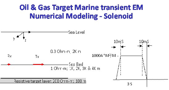 |
| Figure 4: Marine earth model and Solenoid system configuration for numerical Modeling. |
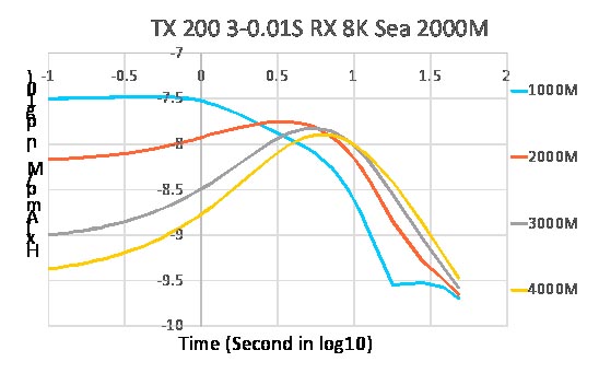 |
| Figure 5 represents the inline magnetic field for the TX and RX separation at 8 kilo-meters after the current is turned off for different thickness of the first layer. The marine earth model and Solenoid system configuration is shown in Figure 4. |
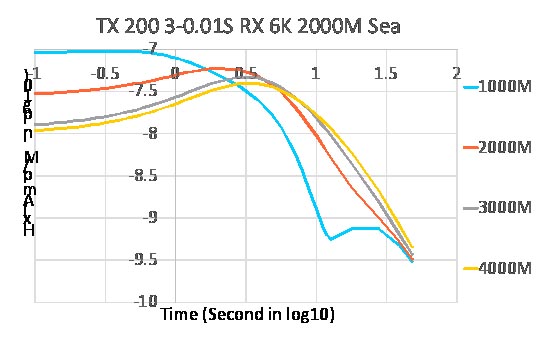 |
| Figure 6 represents the inline magnetic field for the TX and RX separation at 6 kilo-meters after the current is turned off for different thickness of the first layer. The marine earth model and Solenoid system configuration is shown in Figure 4. |
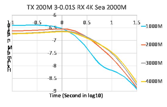 |
| Figure 7 represents the inline magnetic field for the TX and RX separation at 4 kilo-meters after the current is turned off for different thickness of the first layer. The marine earth model and Solenoid system configuration is shown in Figure 4. |
| Conclusion |
| From the above modeling results, the solenoid configuration shows more distinguishable signal to the target layer compared to that from VEL. |
| Contact: |
| 该 Email 地址已受到反垃圾邮件插件保护。要显示它需要在浏览器中启用 JavaScript。 for Tech Questions. |
| 该 Email 地址已受到反垃圾邮件插件保护。要显示它需要在浏览器中启用 JavaScript。 for system leasing or purchasing. |